PO Box 112, Paradise Point, Queensland 4216, Aus
THERMODYNAMIC MODELING
An initial task for new design and one for improvement of process is the mathematical modelling of process systems. Here we use software to determine the system variables after election of key process design parameters.
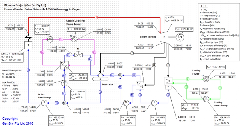
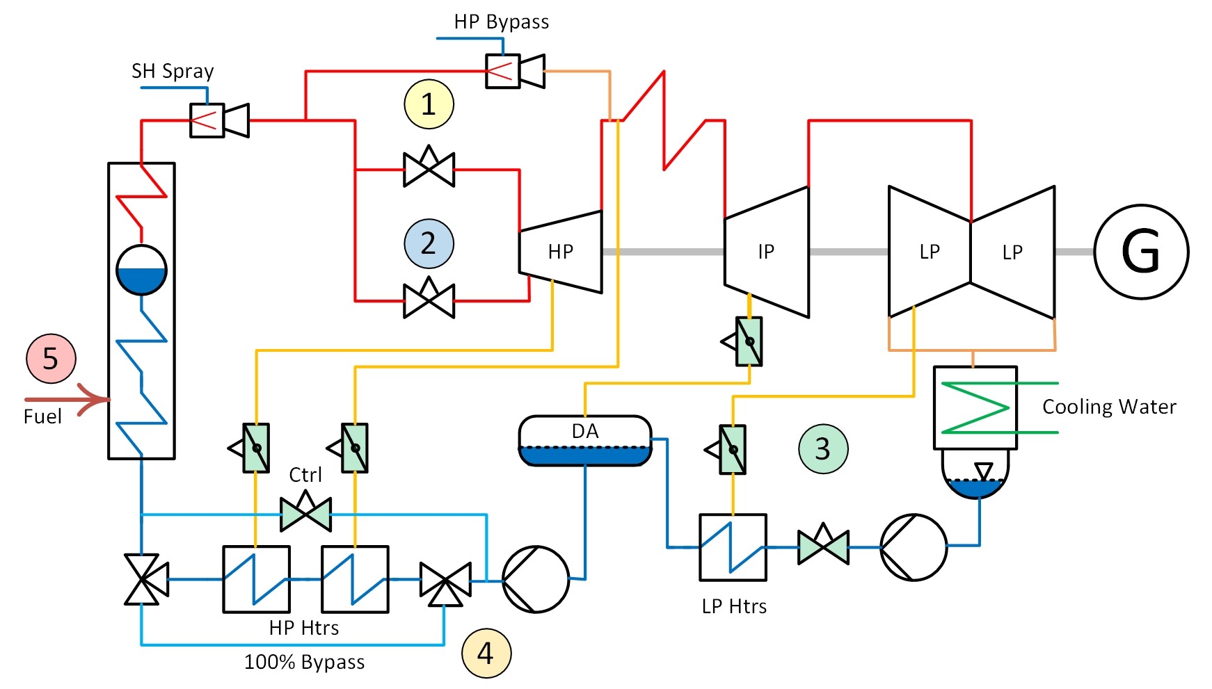
As can be seen in the process model above. We have generated a steam boiler diagram for a small biomass plant. As the client is looking for the highest output and best efficiency we can easily determine the terminal parameters and then calculate the balance. For example, here we know we will achieve about 8MW based on the CV of the fuel and the quantity available. Knowing we are looking at 8MW it is clear there is no need to go to high steam pressure and temperature levels as the cost would out way the small benefit.
Keeping the design in line with base standard none exotic metals we elected to hold the boiler steam outlet temperature at 455 DegC and a pressure of 67.5 Bara. Knowing that our Cooling water temperature is about 25 DegC we can then use the model to generate the other parameters. Of course there is more work than above to this.
This drawing also illustrates the addition of a Cogeneration energy take off. In order to not waste the high purity boiler, water a closed circuit using a plate heat exchanger is designed. as below a stream of water is extracted after the DA and passed by a circulating pump through the heat exchanger. A second potable water pump is used to supply the potable water to the process. For this model the energy required by the process is known which allows the model to balance the energy requirements in the closed loop.
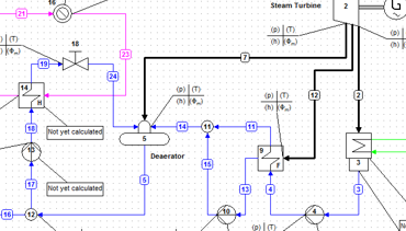
With the Cogeneration system modelled the final stage is to determine the impact on the main process following removal of that heat from the Cogeneration. The findings can then be combined with current utility costs to determine if the cogeneration would add value to the asset. Capex would also be included in this calculation as the new side stream closed loop system would have a cost impact.

